


If you're seeing this message, it means we're having trouble loading external resources on our website. If you're behind a web filter, please make sure that the domains *.kastatic.org and *.kasandbox.org are unblocked.

Updated February 10, 2020 By Kevin Beck Reviewed by: Lana Bandoim, B.S.
A simple electrical circuit contains a source of voltage (a power supply, such as a battery, generator or the utility wires coming into your building), a wire to carry current in the form of electrons, and a source of electrical resistance. In reality, such circuits are rarely simple and include a number of branching and re-joining points.
Along the branches, and sometimes along the main trunk of the circuit, items such as household appliances (lamps, refrigerators, television sets) are placed, each drawing current to keep itself going. But what exactly happens to the voltage and current within a given electrical circuit set-up from a physics standpoint when each resistor is encountered and the voltage "drops"?
Ohm's law states that current flow is voltage divided by resistance. This can apply to a circuit as a whole, an isolated set of branches or to a single resistor, as you'll see. The most common form of this law is written: V = IR
Circuits can be arranged in two basic ways.
Series circuit: Here, current flows entirely along one path, through a single wire. Whatever resistances current encounters along the way simply add up to give the total resistance of the circuit as a whole:
RS = R1 + R2 + ... + RN (series circuit)
Parallel circuit: In this case, a primary wire branches (shown as right angles) into two or more other wires, each with its own resistor. In this case, the total resistance is given by:
1/RP = 1/R1 + 1/R2 + ... + 1/RN (parallel circuit)
If you explore this equation, you find that by adding the resistances of the same magnitude, you decrease the resistance of the circuit as a whole. (Picking 1 ohm, or 1 Ω, makes the math easier.) By Ohm's law, this actually increases the current!
If this seems counterintuitive, imagine the flow of cars on a busy highway served by a single tollbooth that backs up traffic for a mile, and then imagine the same scenario with four more tollbooths identical to the first. This will plainly increase the flow of cars despite technically adding resistance.
If you want to find voltage drops across individual resistors in a series, you proceed as follows:
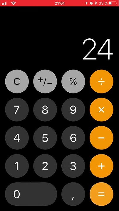
Example: A 24-V power source and three resistors are connected in series with R1= 4 Ω, R2= 2 Ω and R3 = 6 Ω. What is the voltage drop across each resistor? First, calculate total resistance: 4 + 2 + 6 = 12 Ω
Next, calculate the current: 24 V/12 Ω = 2 A
Now, use the current to calculate the voltage drop across each resistor. Using V = IR for each, the values of R1, R2 and R3 are 8 V, 4 V and 12 V.
Example: A 24-V power source and three resistors are connected in parallel with R1= 4 Ω, R2= 2 Ω and R3 = 6 Ω, as before. What is the voltage drop across each resistor?
In this case, the story is simpler: Regardless of the resistance value, the voltage drop across each resistor is the same, making the current the variable that differs across resistors in this case. This means that the voltage drop across each is just the total voltage of the circuit divided by the number of resistors in the circuit, or 24 V/3 = 8 V.
See the Resources for an example of an instance in which you can use an automatic tool to calculate the voltage drop in a kind of circuit arrangement called a voltage divider. Voltage drop is the decrease of electrical potential along the path of a current flowing in an electrical circuit. Voltage drops in the internal resistance of the source, across conductors, across contacts, and across connectors are undesirable because some of the energy supplied is dissipated. The voltage drop across the electrical load is proportional to the power available to be converted in that load to some other useful form of energy.
For example, an electric space heater may have a resistance of ten ohms, and the wires that supply it may have a resistance of 0.2 ohms, about 2% of the total circuit resistance. This means that approximately 2% of the supplied voltage is lost in the wire itself. An excessive voltage drop may result in the unsatisfactory performance of a space heater and overheating of the wires and connections.
National and local electrical codes may set guidelines for the maximum voltage drop allowed in electrical wiring to ensure efficiency of distribution and proper operation of electrical equipment. The maximum permitted voltage drop varies from one country to another.[1] In electronic design and power transmission, various techniques are employed to compensate for the effect of voltage drop on long circuits or where voltage levels must be accurately maintained. The simplest way to reduce voltage drop is to increase the diameter of the conductor between the source and the load, which lowers the overall resistance. In power distribution systems, a given amount of power can be transmitted with less voltage drop if a higher voltage is used. More sophisticated techniques use active elements to compensate for excessive voltage drop.
Consider a direct-current circuit with a nine-volt DC source; three resistors of 67 ohms, 100 ohms, and 470 ohms; and a light bulb—all connected in series. The DC source, the conductors (wires), the resistors, and the light bulb (the load) all have resistance; all use and dissipate supplied energy to some degree. Their physical characteristics determine how much energy. For example, the DC resistance of a conductor depends upon the conductor's length, cross-sectional area, type of material, and temperature. If the voltage between the DC source and the first resistor (67 ohms) is measured, the voltage potential at the first resistor will be slightly less than nine volts. The current passes through the conductor (wire) from the DC source to the first resistor; as this occurs, some of the supplied energy is "lost" (unavailable to the load), due to the resistance of the conductor. Voltage drop exists in both the supply and return wires of a circuit. If the voltage drop across each resistor is measured, the measurement will be a significant number. That represents the energy used by the resistor. The larger the resistor, the more energy used by that resistor, and the bigger the voltage drop across that resistor. Ohm's Law can be used to verify voltage drop. In a DC circuit, voltage equals current multiplied by resistance. V = I R. Also, Kirchhoff's circuit laws state that in any DC circuit, the sum of the voltage drops across each component of the circuit is equal to the supply voltage. In alternating-current circuits, opposition to current flow occurs because of resistance, just as in direct-current circuits. However, alternating current circuits also include a second kind of opposition to current flow: reactance. The sum of oppositions to current flow from both resistance and reactance is called impedance. Electrical impedance is commonly represented by the variable Z and measured in ohms at a specific frequency. Electrical impedance is computed as the vector sum of electrical resistance, capacitive reactance, and inductive reactance. The amount of impedance in an alternating-current circuit depends on the frequency of the alternating current and the magnetic permeability of electrical conductors and electrically isolated elements (including surrounding elements), which varies with their size and spacing. Analogous to Ohm's law for direct-current circuits, electrical impedance may be expressed by the formula E = I Z. So, the voltage drop in an AC circuit is the product of the current and the impedance of the circuit.
|

A voltage drop exists if there is ____ between two points in a circuit.
Pos Terkait


Copyright © 2024 kemunculan Inc.